


How we assissted, purchased and upgraded our electronics with the past, present and future in mind (published January 2015)
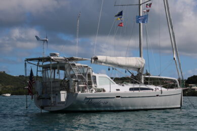
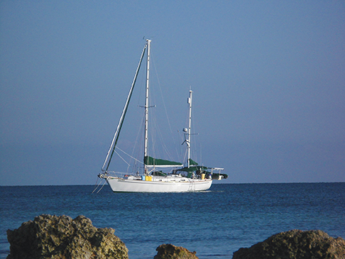
After three and a half years in a Colorado cornfield, the complete restoration and refit of our Pearson 424 ketch, Regina Oceani (Queen of the Ocean), was almost complete. Trucked 2,000 miles to Titusville, Florida for launching, she rested just five minutes from our rented house in Melbourne, Florida. And one of the final considerations we had was in how to bring her 20-year-old electronics into this decade.
When it comes to marine electronics, things change quickly and often. Every major boat show seems to highlight a new “must-have” innovation. As with TVs and laptop computers, there appears to never be a “right time” to take the leap and commit to new electronics—as soon as the new gear is installed, something “better” comes on the market.
With the must-have/right time/quality conundrum in mind, we had to set some criteria for selecting new electronics, “now.” To do this, we started by assessing what was already on the boat that might stay, either as back-up gear or to be integrated in with the new system, and what should definitely go. Our goal was to have redundancy of systems while gaining modern sailing-savvy instrumentation, AIS reception and display, and radar overlay of charts.
ASSESSING THE OLD
The Queen had a full set of Raytheon/Raymarine instruments and autopilot spanning the ST50 through ST70 generations but no chartplotter. There were three NMEA-0183 speaking GPS systems on board: an ST50 GPS display, a first generation Magellan unit and a Furuno GP-32— only the Furuno unit is still in production.
In the cockpit, each of the instruments was specialized and independent with one black-and-white numeric or analog display each for depth, wind, speed, GPS and compass. Depth and speed were repeated at the nav station with a two-line “multi-display.” Primary navigation was provided by a laptop computer at the nav station with control and display duplicated on an early generation, hard-to-read-in-full-daylight tablet computer at the binnacle (see “A Better Way” BWS December 2005).
This interfaced with the ST7000 control head of the Autohelm 100 autopilot computer. A completely independent CPT autopilot could steer the boat via a toothed belt on the wheel. In the end, we kept the depth and multi displays, the Furuno GPS and the back-up autopilot as redundant systems—pretty much everything else, including the very old Raytheon radar went to the flea market. The Autohelm drive unit, which was properly sized for our boat, is a universal component and we retained that as the muscle end of the new autopilot system.
ASSESSING THE NEW
While exploring new chartplotter and instrument systems, the term “multi-function display” or “MFD” quickly entered our vocabulary. Everything can be displayed on the MFD including charts, radar, depth, wind, and even videos, saved PDF manuals and tide tables. There are plenty of quality integrated systems on the market, but in light of the sailing specific features, seemingly lacking from all other systems, the B&G systems stood out for us.
B&G has a reputation for providing the best sailing optimized instruments and they still produce a full line of racing instruments and computers. For our cruising boat, the Zeus Touch line of MFDs and the Triton line of color display heads provided all the features we would ever need at about the same cost as other similarly sized touch display systems.
The unique features of the B&G system include SailSteer, which is an integrated single screen that is truly optimized for sailing. On one screen, compass, course, wind, current/tide, opposite tack, and name of and course to waypoint are all displayed. While tacking towards a waypoint, one can see the waypoint bearing move around the “heading-up” compass ring. When the waypoint bearing mark and the opposite tack mark align, you know your next tack will take you directly to the waypoint—real-time current is even considered in this automatic calculation. This really takes the guesswork out of knowing when to tack. Strangely, although true wind is displayed on this screen, apparent wind is not but is clearly displayed on the Triton displays. Given the choice, I would select apparent over true as the wind to display.
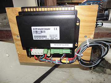
With regards to our primary autopilot, we explored having the Zeus touch MFD feed NMEA-0183 data to the old Raytheon system. While this would work, all of the benefits of a completely integrated system would be lost. B&G instruments can directly drive the highly respected line of Simrad autopilots. That is to say, any of the Triton or Zeus displays can serve as a control head for the Simrad autopilot computers—introducing another level of redundancy to our systems. In the end, taking the leap of replacing the old AP head and computer turned out to be a smart move as the new B&G system, which we call “Barry”, is easier to use, steers more efficiently and consumes less power.
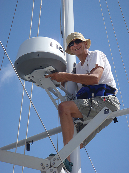
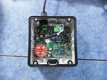
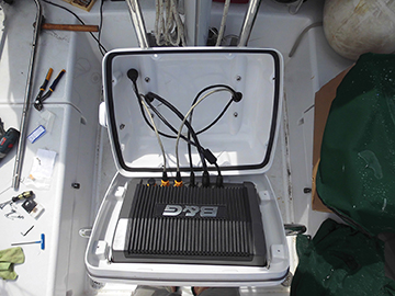
Another potential area for power saving was with the radar system. The B&G 4G radar system uses broadband transmission instead of microwaves. This has several advantages over traditional radar including very high up-close resolution—remember all collisions happen up close—, no dangerous microwave radiation, instant on versus long warm-up periods, and very low power consumption. It is amazing to watch paddle boarders go by on radar or to spot empty slips around a corner in a marina. The trade-off is some long range resolution that might be handy for tracking distant squalls, but we found that tracking storms around eight miles away was a cinch.
WIRELESS DISPLAYS & WHERE TO PUT THEM
By connecting the low-cost GoFree Wi-Fi adapter to the Zeus Touch MFD with a LAN cable, anything displayed on the MFD can also be displayed on an iPad, iPhone, Android or tablet after downloading a free app. The MFD can also be controlled by touch on these mobile devices. What’s more, some of the touch features are even better on these devices than on the MFD itself—pinch zooming, for example, can only be done on the mobile devices. (Note: The Zeus+ Touch now has pinch zooming). With this level of control and mobility, tablets are perhaps more economical and versatile than adding an additional MFD.
The old displays, of course, left holes to fill but we really did not need as many displays as before since each color Triton display can convey so much information on a single screen. In the cockpit we opted to replace five dedicated instrument heads with two Triton displays. At the nav station we added a Triton display to provide all necessary—and all available—data with a single display.
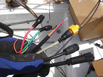
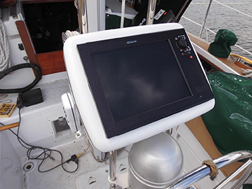
The main display and center of navigation became the 12-inch Zeus Touch MFD mounted at the binnacle. This required a new approach; the binnacle guard was replaced with a taller offset one from Ocean Equipment that slipped right into the mounts on our Edson binnacle and holds their Navpod, which is precut to receive the Zeus Touch. After using an angle grinder to cut holes in the binnacle guards to match the holes in the Navpod, all six cables (NMEA-2000, two LAN cables, video/NMEA-0183, power and cable for our remote access VHF microphone) ran down inside the two one-inch diameter tubes, but not without some trial and error sorting of the size of cables, cable connectors and order of insertion of the varied cables.
GETTING ON THE BUS
The prior owner of our boat went through several generations of electronics but never removed the old wires; he just cut the wires and installed the new wires with new wire ties over the old ones. An early project when we got the boat was removing all the old unused wires—two 50-gallon trash cans full!
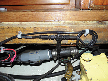
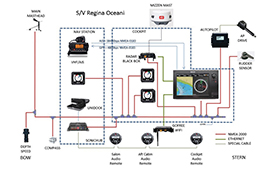
Now, finally moving to NMEA-2000 bus-based architecture, we should be done replacing wires for our electronics. Planning any bus layout should be done carefully. Each end of the bus must have a terminator. The masthead instrument has an internal terminator so it should serve as one end of the bus. This was a little counterintuitive as the speed/depth sensor is further forward on the boat than the mast. The male-female flow of the cables and tee connectors needs to be continuous from one end to the other, which means you should start installing the bus at one end of the boat and move piece-by-piece to the other end.
We started at both ends and moved to the middle, finding that male connectors don’t join to male connectors. But we only had to move a few cables to correct the error. Having the right collection of cables and connectors required some help from our B&G dealer. While the Simnet and Micro-C versions of NMEA-2000 play perfectly well together, where they mix such as at the Autopilot, a Simnet to Micro-C cable must be ordered. Don’t be surprised if, as a result of some of the devices coming with cables and bus starter kits, you end up with several extra bus terminators and tees.
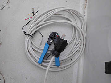
In addition to the NMEA-2000 bus, two Ethernet (LAN) cables carry higher bandwidth chart and radar data between the radar black box, the go-free wireless adapter and the Zeus Touch MFD. Since the Zeus Touch 12 provides three LAN ports, no LAN hub was needed. One cable from the Zeus Touch provides two video inputs and the NMEA-0183 in and out connections. AIS data flows via NMEA-0183 from our Standard Horizon Matrix AIS VHF radio to the MFD at 38,400 bits per second. In the other direction, the MFD provides GPS data to the radio at 4,800 bps.
While not as “plug-n-play” as NMEA-2000, it was simple enough to configure on the MFD and radio. Vessel ID, speed and direction display closest point of approach (CPA), and time to CPA. And even destination port and planned arrival time can be displayed on the MFD simply by touching the triangle symbol of a boat. This came in handy as we could call directly to close approaching freighters on our shakedown cruise, “Good morning captain, we show our boat having a tenth mile closest point of approach in seven minutes with you, will you be turning or slowing as you approach port?”
GETTING THE TUNES
We have used our laptop computer as a jukebox on the boat with the touchscreen tablet in the cockpit able to select the songs and control the volume. We did not want to lose this essential luxury.
Navico (the parent company of B&G, Simrad and Lowrance) and Fusion Electronics provide a well-integrated solution that includes an AM/FM radio, optional Sirius radio if desired, and can connect to an iPod, iPhone, Android or even a USB flash stick in a waterproof “Uni-Dock.” The Simrad (or Lowrance) SonicHub is a black box audio controller with two sets of stereo amplifiers and an output for a third amplifier. Each of these outputs represents a separately controllable “zone” within which the volume can be independently controlled, but the same music plays to all of the zones.
The Zeus Touch master volume control can be set to control one, two or all three zones. We used an old car stereo amplifier for the third zone. By adding three Fusion MS-WR600C wired control heads to the system—one each in the cockpit, aft cabin and saloon—we can control the audio in each zone even while the Zeus system is off. It’s a great solution but not perfect as the MFD and remote control heads sometimes seem to argue with each other for control with the Zeus (head of the gods after all), turning the audio back on after the remotes (lesser gods?) turns it off. The Zeus always wins until it is turned off. B&G tells us this will be fixed in an future firmware update.
PUTTING THINGS TO THE TEST
The Zeus system comes with integrated 2D and shaded relief Insight charts as well as basic Navico charts. The Insight charts seemed very complete for our cruising area. Also, a micro-SD slot is provided in the Zeus MFD for Navionics Platinum Plus, TurboView charts and some others.
Before the autopilot can be used, it must be commissioned using first an at-the-dock procedure and then an underway procedure, the latter involving motoring the boat slowly in a circle at a displayed turning rate.
We found our wind instrument was intermittent and traced that down to a bad connector on the masthead cable. B&G quickly replaced this cable and it has been utterly reliable since then.
The cockpit Triton displays, one set to depth/speed and the other to wind, are very intuitive with the wind display providing an amazing amount of easy to consume information including true and apparent wind speed and angle, cross current direction and speed, autopilot heading and tack angles. It was easy to set the lighting on these display to sync with the MFD so that dimming the MFD or setting it to night mode instantly set the Triton displays to the same lighting level.
The feast for the eyes, though, is the Zeus Touch 12 display. What is displayed on each page can be selected from several pre-configured layouts or completely customized within one, two, three or four windows per page. Multiple custom display configurations can be saved and quickly selected for display. We tend to sail with the screen split displaying both SailSteer and chart screens.
With the fluxgate compass installed, the radar display can be overlaid on the chart and showed perfect tracking. The autopilot control window can be invoked by several means and dismissed when not needed. On an upwind leg we found the autopilot steering to the wind wasted few movements in tracking the wind shifts and actually out sailed an adjacent boat. We were quickly able to configure our preferences such as range rings and vessel extension lines and were impressed with the level of configurability of the displays.
The layline feature is truly technology resembling magic. With tidal flow correction turned on, the system can provide constantly updated tack and jibe lines off the next waypoint, including early and late tack lines as well within the current conditions and performance of the boat. This can save time and help avoid premature tacks that can result in additional tacks.
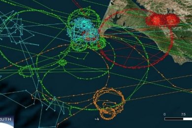
On our first cruise at sea with the system, as we normally do, we practiced crew overboard drills. After a few hand steered figure eights we were able to review our tracks on the MFD and see just how well we had done in optimizing our returns to the MOB. Then we decided to see what would happen if we let Barry (the autopilot) return us to the MOB—after all, Barry, once seeing an MOB mark set, asks if you would like him to navigate back to the MOB. Now, Barry needs some sailing safety lessons, as he jibed us from a broad reach instead of tacking the boat. The support folks at B&G agreed that could have been very dangerous and potentially damaging to the boat in hairy conditions and promised to consider working on the software logic to avoid jibing when returning to an MOB mark. After all, the MFD has all the data and power to figure that out.
TYING TO THE COMPUTER
When planning a route, I prefer to do the work on the laptop computer in a program such as OpenCPN and then import the waypoints and routes to the chartplotter. With our old laptop running The Cap’n navigational software, loading waypoints and routes to our 20 plus year old autopilot was just a matter of pushing a button. So far the only way we have found to transfer waypoints and routes from our laptop running OpenCPN to the MFD has been “sneaker net” using a micro-SD card. With the GoFree wireless system we are waiting for a simple wireless upload mechanism but this has not yet been available. Since there are levels of “openness” of the B&G system available for developers, perhaps an OpenCPN to Zeus wireless or even a wired upload solution using NMEA-0183 will become available in the future.
HAPPINESS IN 2014
Moving to modern digital electronics has been a boon to the Queen, but now Jill sometimes calls to Barry in her sleep. Leveraging the old autopilot drive has worked out perfectly and having two color cockpit displays provides more and clearer data than five monochrome displays had previously. All data is now available on a single display at the nav station and the 12-inch MDF in the cockpit brings everything including AIS and radar together in an easy to use, easy to see—day or night—and easy to understand display. And while we did have, and are still experiencing, some growing pains in getting the entire system to function properly, I’m confident this would be the case with any major update in electronics.
After two weeks aboard cruising on the Atlantic and in the Florida Keys, Jill is in love with the B&G instruments, especially in tight ICW channels, and I am still learning about all of their features. And yes Honey, I can turn down the music.
For over a decade now, Pete Dubler has been writing for BWS about projects on his Pearson 424 including articles in this series detailing her complete restoration and refit. During 2015, under a phased retirement program, Pete and his wife Jill will spend more time shaking out S/V Regina Oceani and plan to depart for worldwide cruising in December 2015.